Revit MEP Tutorial 1
Revit MEP 2025
introduction
This tutorial is about learning how to use Revit MEP 2025 for cooling load calculation. Every day, more people are using Revit MEP because it is very helpful in HVAC and MEP work. Revit MEP 2025 is even better and has many new features. In this tutorial, we will learn step by step how to calculate the cooling load using Revit MEP 2025. It will be easy to follow and useful for students and beginners . in this tutorial of Revit MEP we focus on how we can import file in Revit MEP and then we can calculate HVAC Load
what is HVAC Load Calculation?
The main purpose of an HVAC system is to maintain a comfortable indoor air environment, which includes thermal comfort and indoor air quality. The amount of heating or cooling needed to maintain comfortable temperature in the indoor space is called the HVAC load. The process of finding the amount of heating and cooling Required is known as HVAC load calculation.
For this purpose, we use different types of software. This tutorial is about Revit MEP. We can use Revit MEP to calculate HVAC cooling and heating loads.
STEP 1 : Open Mechanical Template
First of all, we can learn a complete about HVAC Load caculation , so we learn how to insert Architecture File in Revit and start working on that so for that First we open Revit MEP 2025 File select new from new from home page of Revit and then select mechanical template as shown in figure
Step 2 insert Revit File
We select insert tab from Ribbon . Now we have this link Revit option of it option. click on it. Select project file, then open this project file. It may take some time.
Step 3 : Open Architecture File
After opening a file click on this file and select this bind link option . Revit Link option are opened so select attached Deatail Levels and then click on ok
step 4 Select Location
In HVAC cooling and heating load calculation, location is very important because it helps us select the latitude and longitude needed to calculate the full cooling load. In the next step, go to the manage tab in the ribbon. In the manage tab, go to the project location panel and click on the location button. After selecting this option, the location and site panel opens. From here, you can select a location in two ways.
First, click on the location option, and a list of cities will appear. You can select any city from this list. The second option is to click on the site, where you can choose the exact location using Internet mapping. After that, click OK. This way, you can select the project location, and the software will automatically calculate the outdoor temperature, daily range, humidity, and all required values.
Default City List
Step 5 Unit Selection
- In the manage tab, we have a settings panel. Select the settings panel.
- In the settings panel, click on the project unit option as shown in the figure.
- The project unit panel will open.
- Here, you will see different disciplines.
- Select the HVAC discipline.
- You will see a list of properties with default units written next to them.
- You can select different units from this list.
- for Air Flow Rate Select CFM
- For Load Select Ton Of Refrigeration
select all these units
Step 6 Project Setting
- In the manage tab, we have a settings panel. Select the settings panel.
- In the settings panel, click on the project information option as shown in the figure.
- in the project information add information about project as shown in figure.
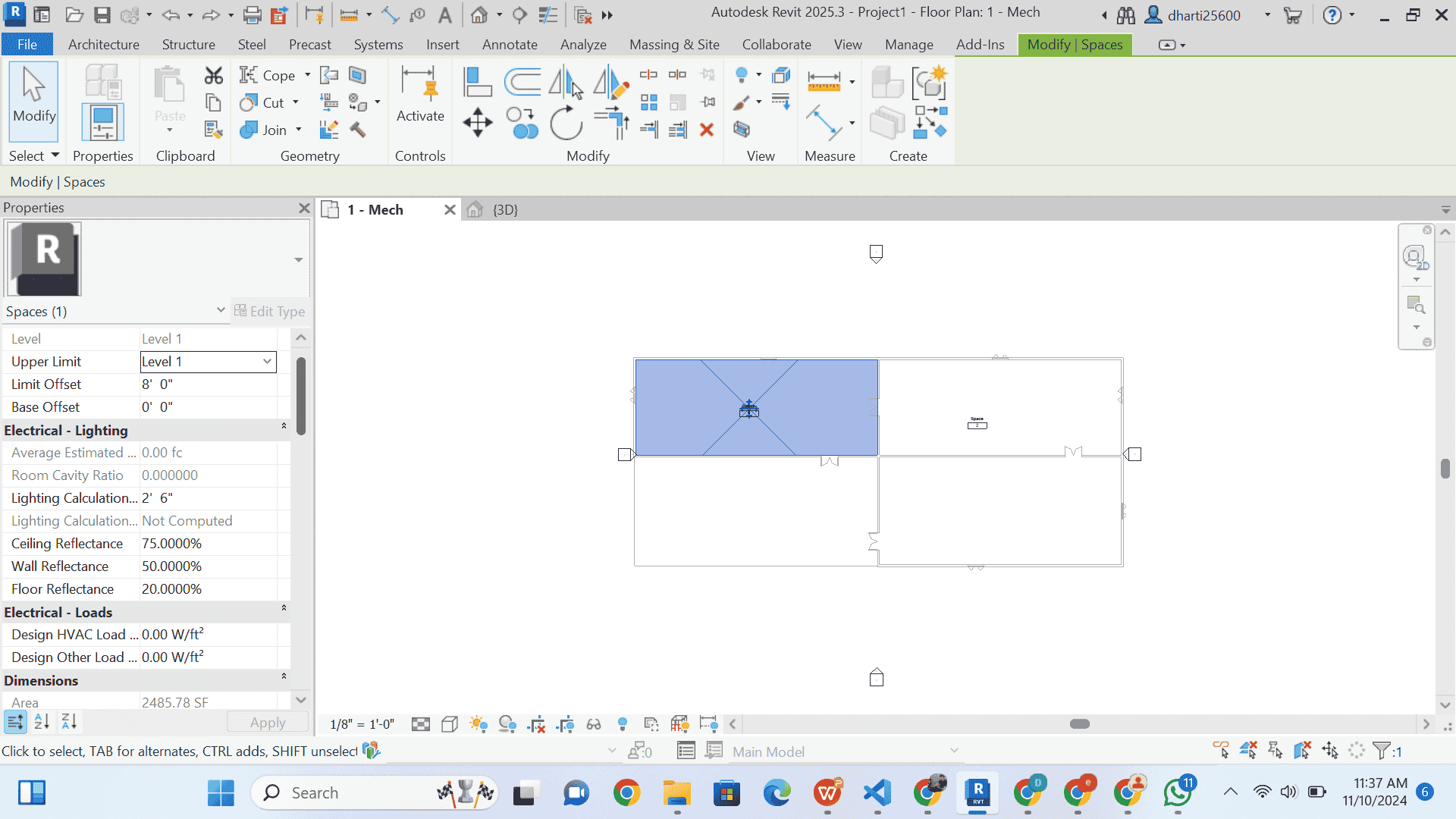
STEP 7 CREATE SPACES
- In the Analyze tab, we have a spaces and zone panel. Select the spaces and zone panel.
- In the spaces and zone panel, click on the spaces option as shown in the figure.
- after selecting spaces information Select Tag on placement option as shown in figure.
now select all spaces
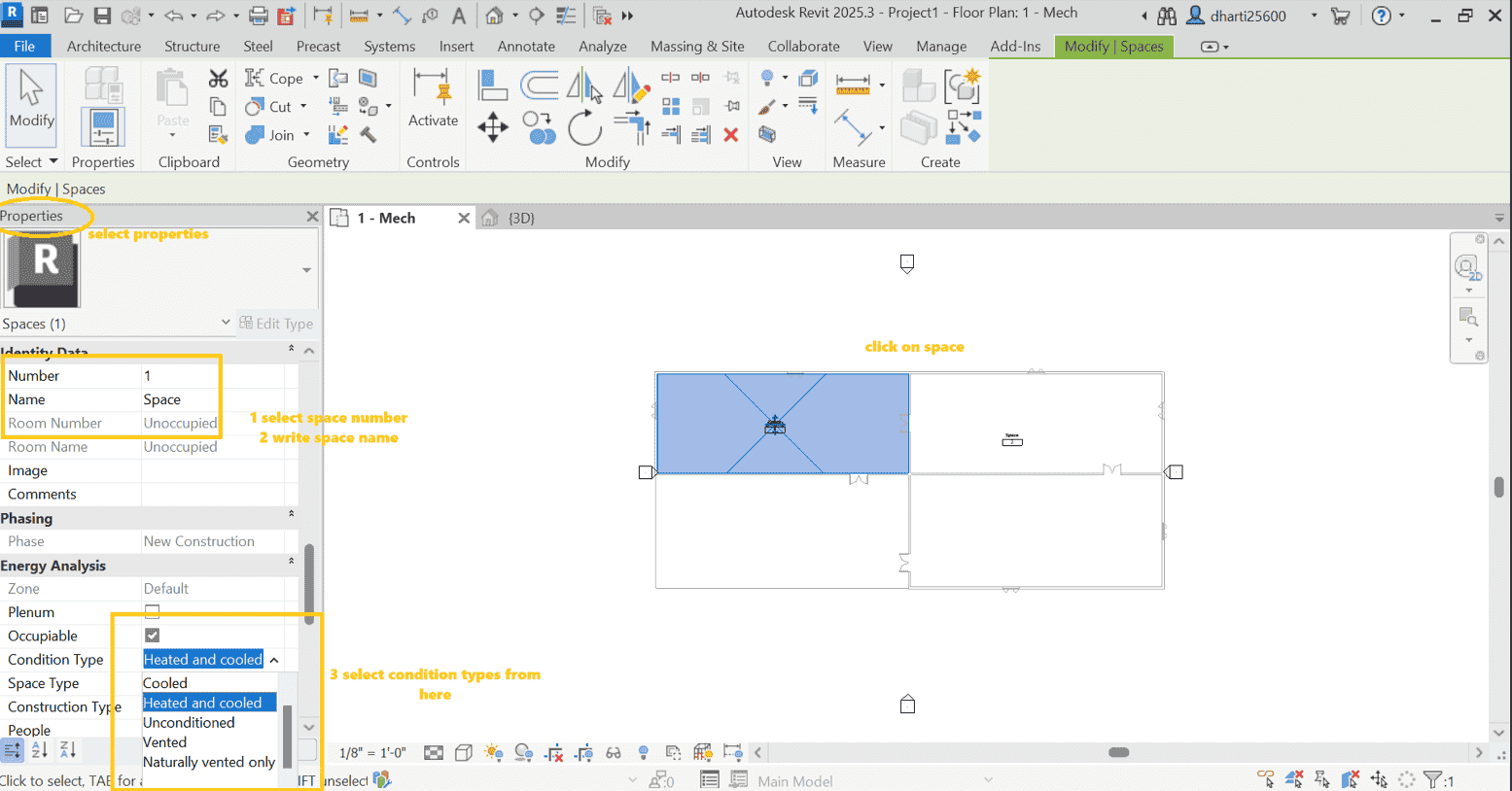
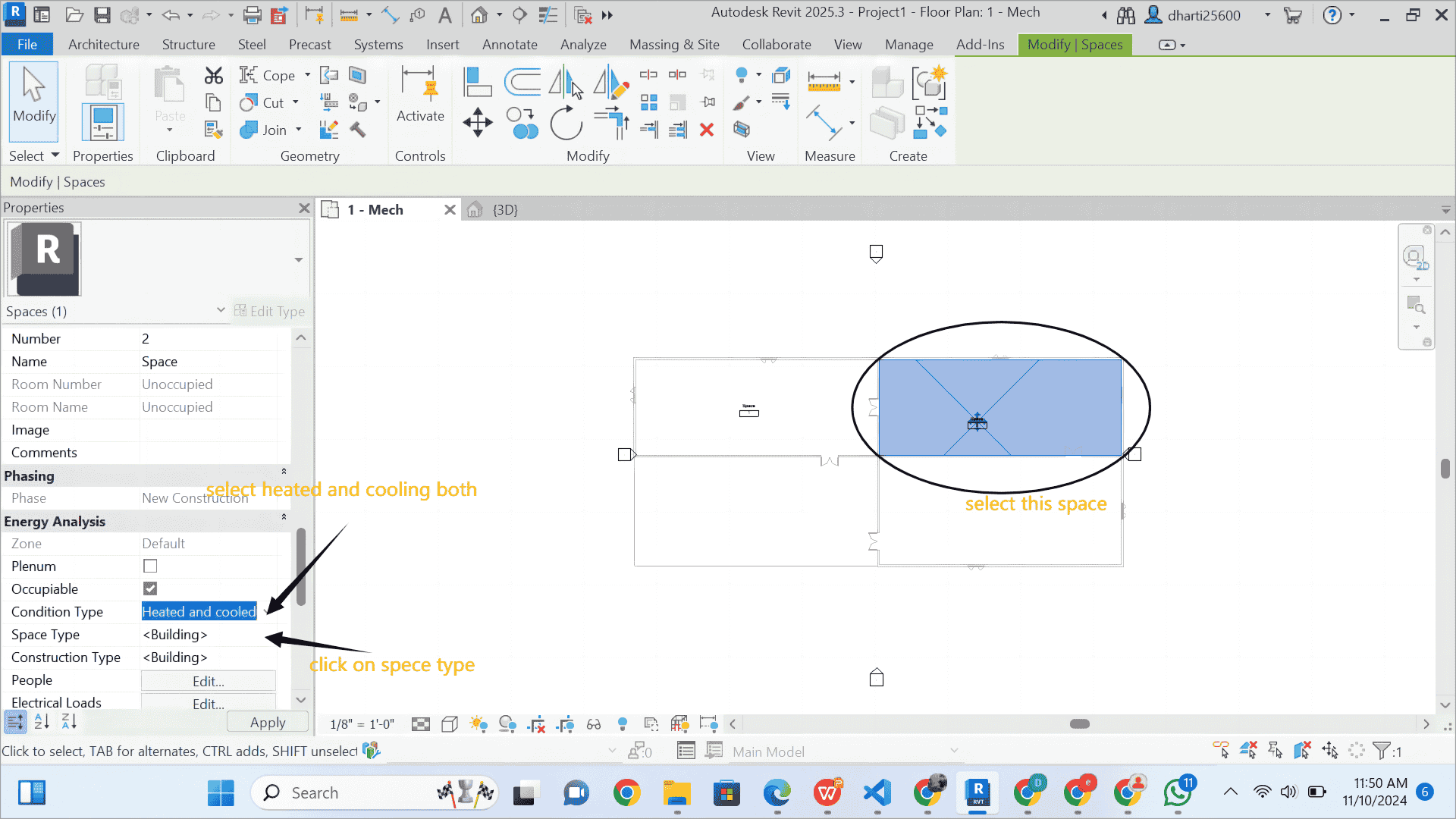
STEP 8 Select SPACES
- Select Space as shown in figure
- go to property palette
- select space name and number option
- then select condition i select both heating and cooling Load
STEP 9 Select Space Type
1 search space type
2 select space type from given tab as i select Room
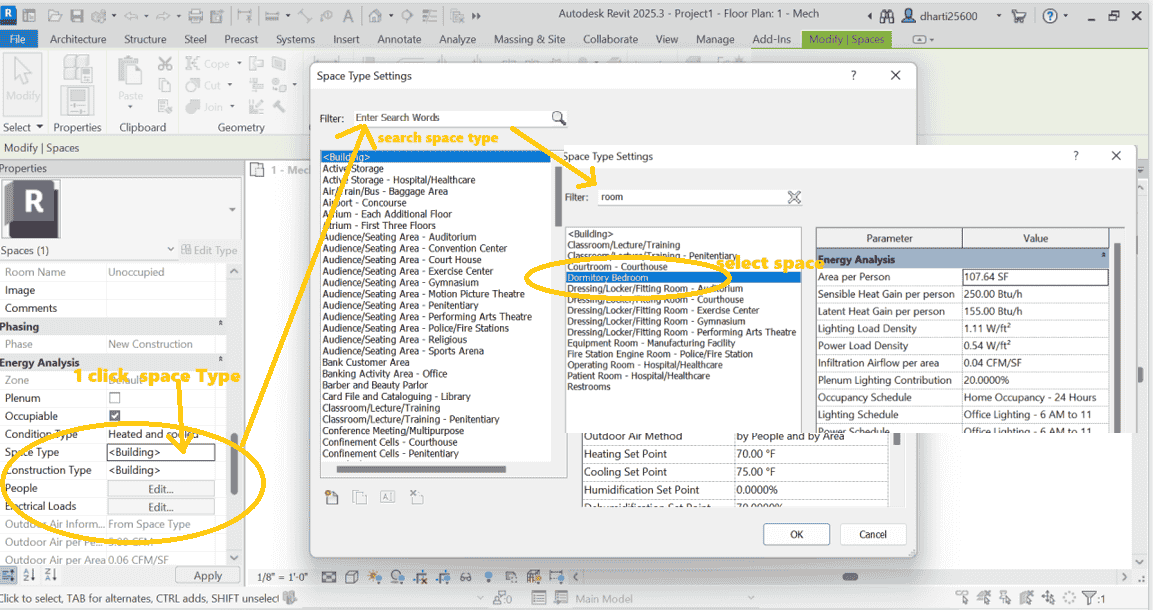
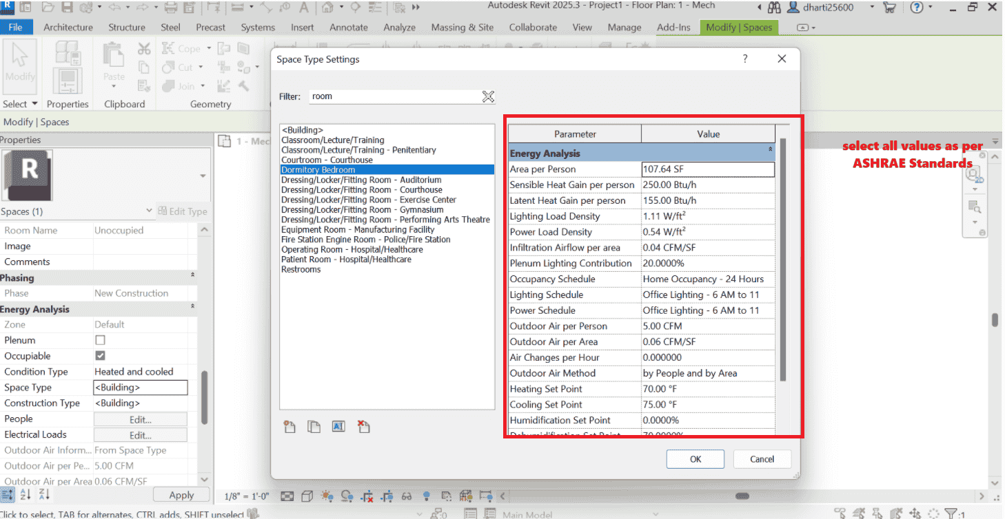
STEP 10 Write all space properties value as per ASHRAE Standard Requirements for Living Room
ASHRAE standard values for a living room in a commercial or residential setting. These values are approximate and should be verified against the current ASHRAE standards (e.g., ASHRAE 62.1 for ventilation, ASHRAE 90.1 for energy efficiency). Living rooms may have slightly varied requirements based on residential or commercial application, so consider these as general guidelines:
1. Area per Person: 100-150 SF per person (ASHRAE 62.1 ventilation rates based on occupancy density)
2. Sensible Heat Gain per Person: 250 Btu/h (typical for low-activity environments like a living room)
3. Latent Heat Gain per Person: 150 Btu/h
4. Lighting Load Density: 0.9-1.1 W/ft² (ASHRAE 90.1 recommendations, adjusted for residential/commercial spaces)
5. Power Load Density: 0.4 W/ft² (covers general electronics usage and typical plug loads)
6. Infiltration Airflow per Area: 0.04-0.08 CFM/SF (based on building envelope tightness, ASHRAE 62.1)
7. Plenum Lighting Contribution: 20% (typical for spaces with plenum return air)
8. Outdoor Air per Person: 5-10 CFM (ASHRAE 62.1 ventilation requirement for residential living areas)
9. Outdoor Air per Area: 0.06-0.12 CFM/SF
10. Air Changes per Hour: 4-6 ACH (for comfortable ventilation in low-activity spaces)
11. Heating Set Point: 68-72°F
12. Cooling Set Point: 74-78°F
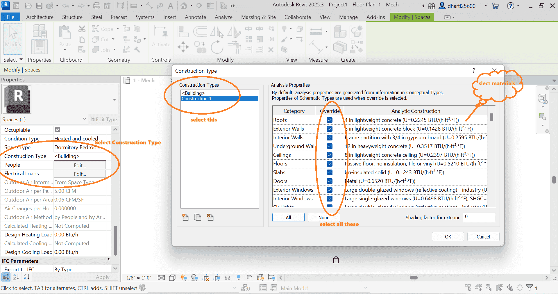
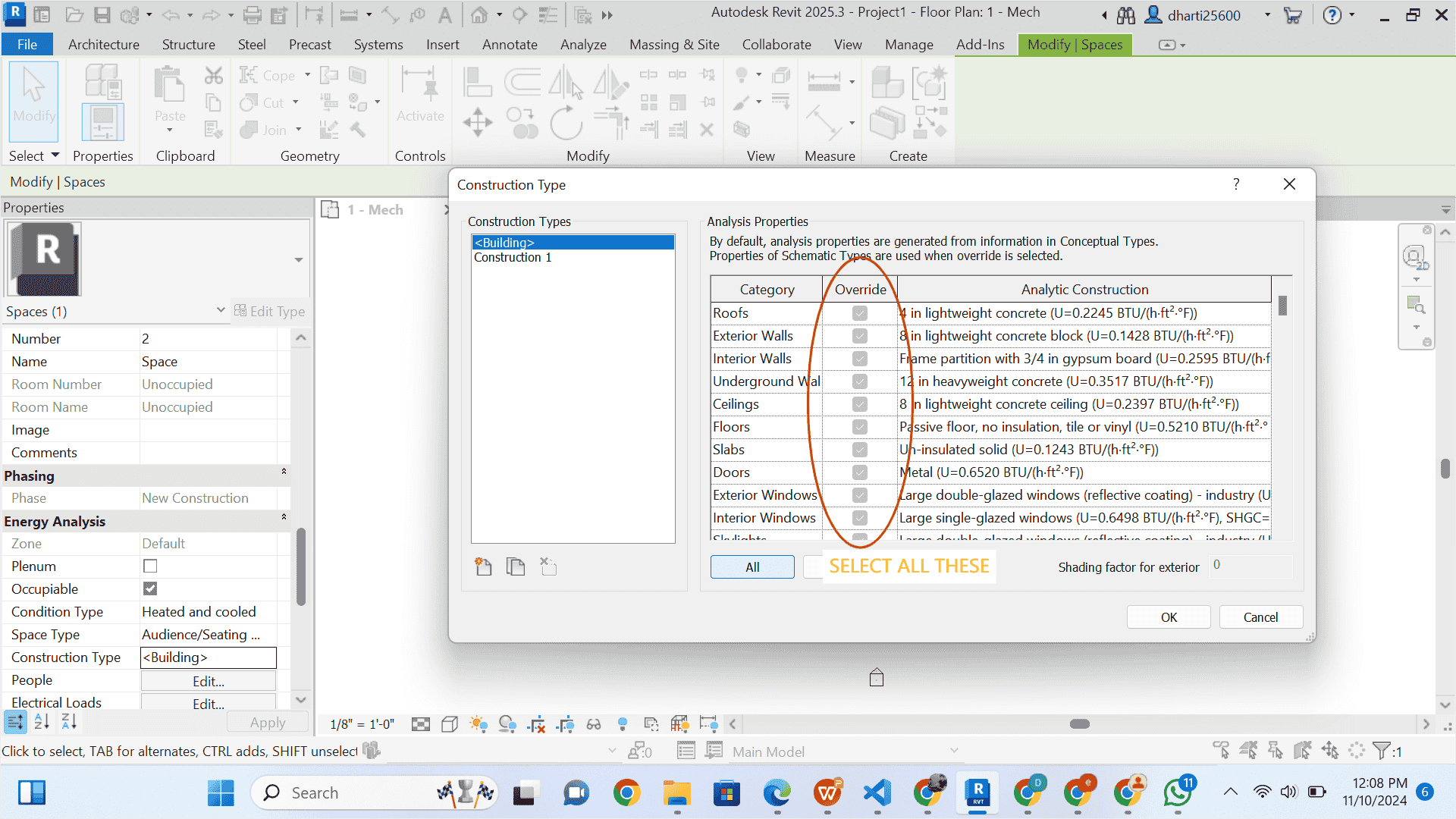
1 Select Construction materials
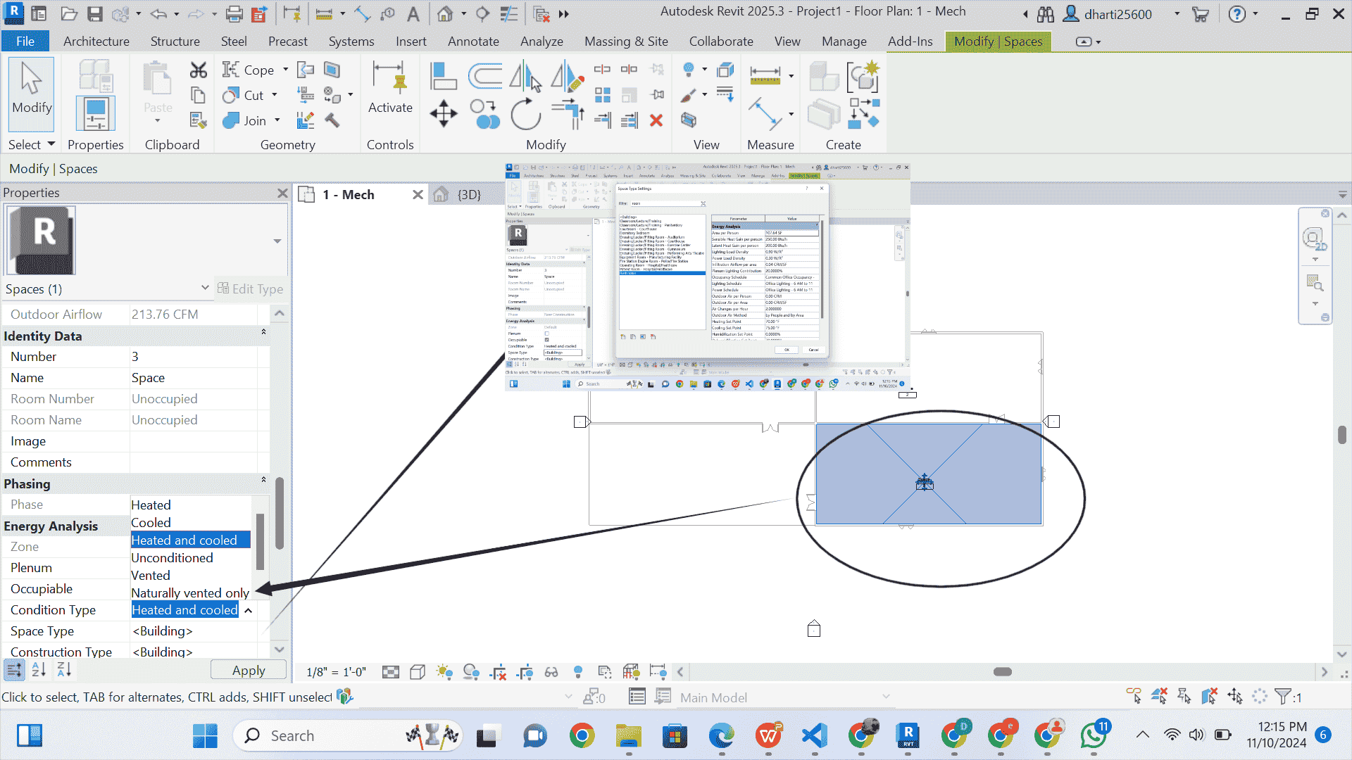
STEP 11 select other space
- in the figure given below select space 2
- Select Heated and cooled from space condition
- click on Space Type
STEP 12 select space Type
1 search space type
2 select space type from given tab as i select Gym
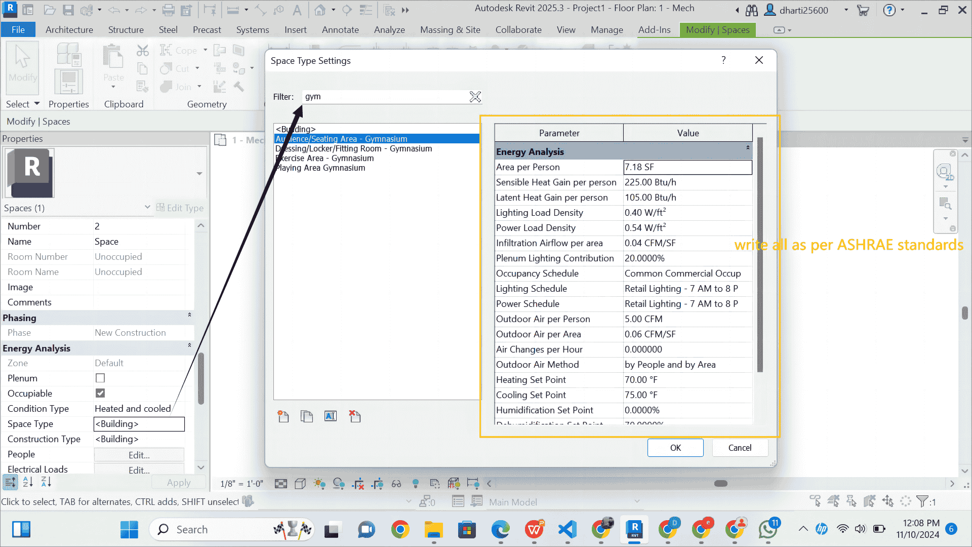
STEP 13 Write all space properties value as per ASHRAE Recommended Values for Gymnasium (Exercise Area)
1. Area per Person: 15-50 SF per person (depends on the type of gym activity and equipment layout)
2. Sensible Heat Gain per Person: 450-550 Btu/h (higher due to physical activity)
3. Latent Heat Gain per Person: 200-300 Btu/h (due to increased perspiration and humidity load from people)
4. Lighting Load Density: 0.9-1.2 W/ft² (ASHRAE 90.1 for gymnasiums)
5. Power Load Density: 0.5-0.75 W/ft² (to account for equipment load and miscellaneous devices)
6. Infiltration Airflow per Area: 0.05-0.08 CFM/SF (based on building tightness and ventilation requirements)
7. Plenum Lighting Contribution: 10-20% (varies based on design and lighting configuration)
8. Occupancy Schedule: Typically 6 AM to 10 PM (commercial gym operations)
9. Lighting Schedule: Gym Lighting 6 AM to 10 PM
10. Power Schedule: Gym Equipment Power 6 AM to 10 PM
11. Outdoor Air per Person: 15-20 CFM (ASHRAE 62.1 ventilation requirement for high-occupancy exercise spaces)
12. Outdoor Air per Area: 0.12-0.2 CFM/SF (based on gym activity intensity)
13. Air Changes per Hour: 4-6 ACH (adequate for ventilation and to maintain indoor air quality in a gym)
14. Outdoor Air Method: By People and Area (combining both occupant and area-based ventilation)
15. Heating Set Point: 65-70°F (adjusted to maintain comfort for physical activity)
16. Cooling Set Point: 72-75°F (lower to accommodate physical exertion and prevent overheating)
17. Humidification Set Point: 30-50% (maintain comfort and prevent excessive dryness)
18. Dehumidification Set Point: 50-60% (prevent high humidity levels, especially in areas with physical activity)
1 Select Construction materials
STEP 14 select space 3
- Select the space as shown in the figure, and follow the steps
- selecting the space first because it is also a restroom.
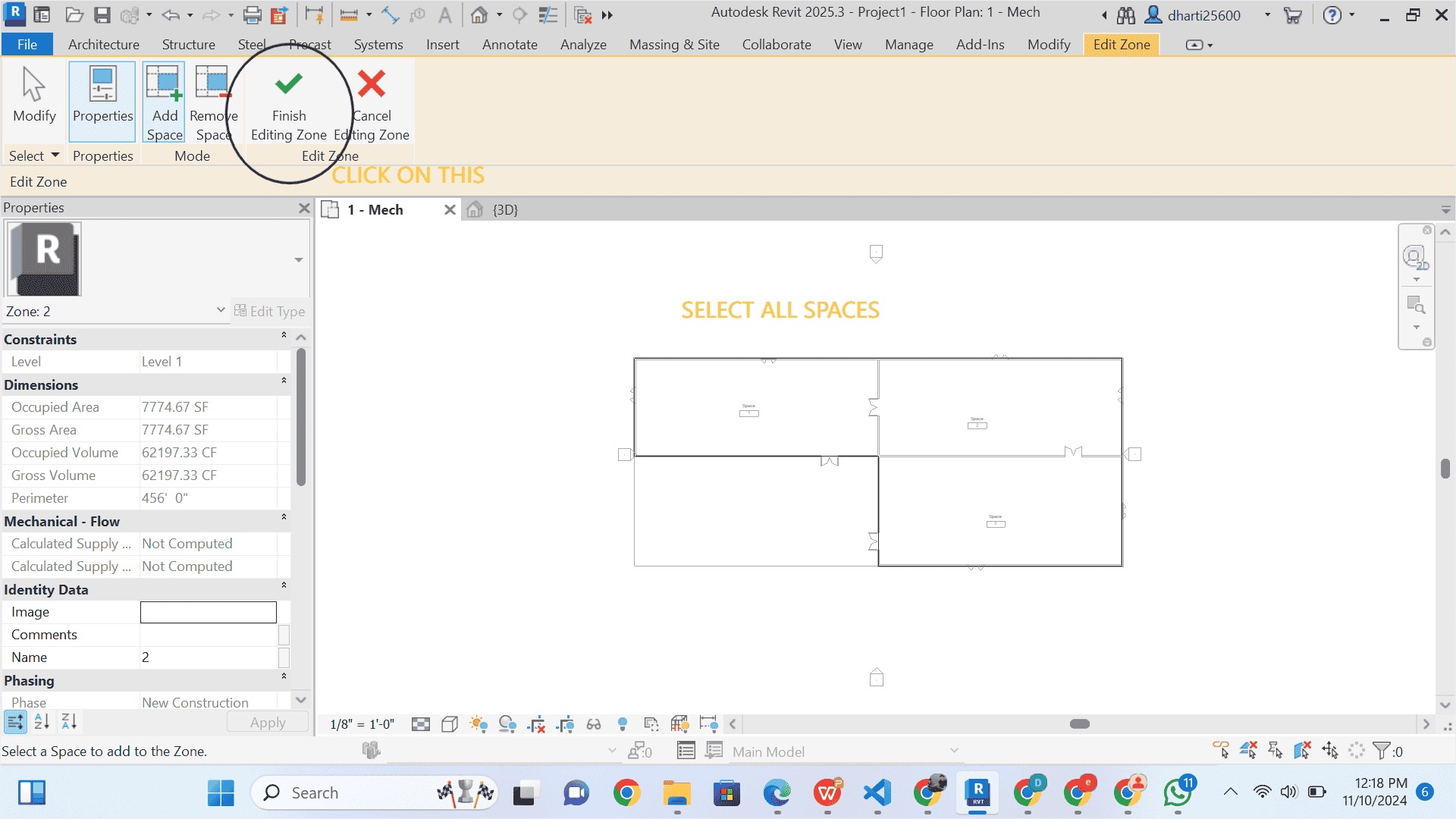
STEP 15 Creating Zones
1 Select space
2 Select Edit zones
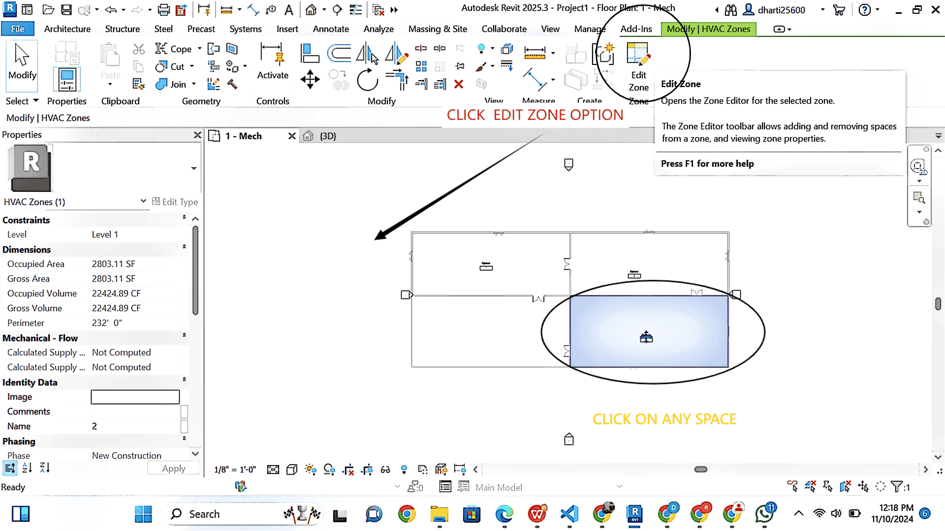
Select all spaces
click on finish Zones
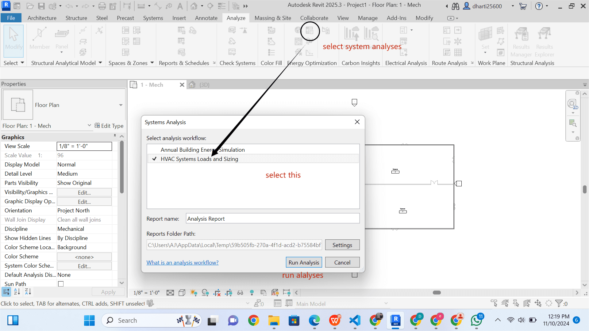
STEP 16 Run Analyses
Run Report Analyses